JCB 930, 940, and 950 Warning Lights: Capture the System Before Calling for Service
How operators of JCB 930, 940, and 950 rough-terrain forklifts can accurately identify engine, transmission, fuel/air, charging, and starting indicators on the instrument panel for safe service dispatch.
STORMY Editorial · · 8 min read
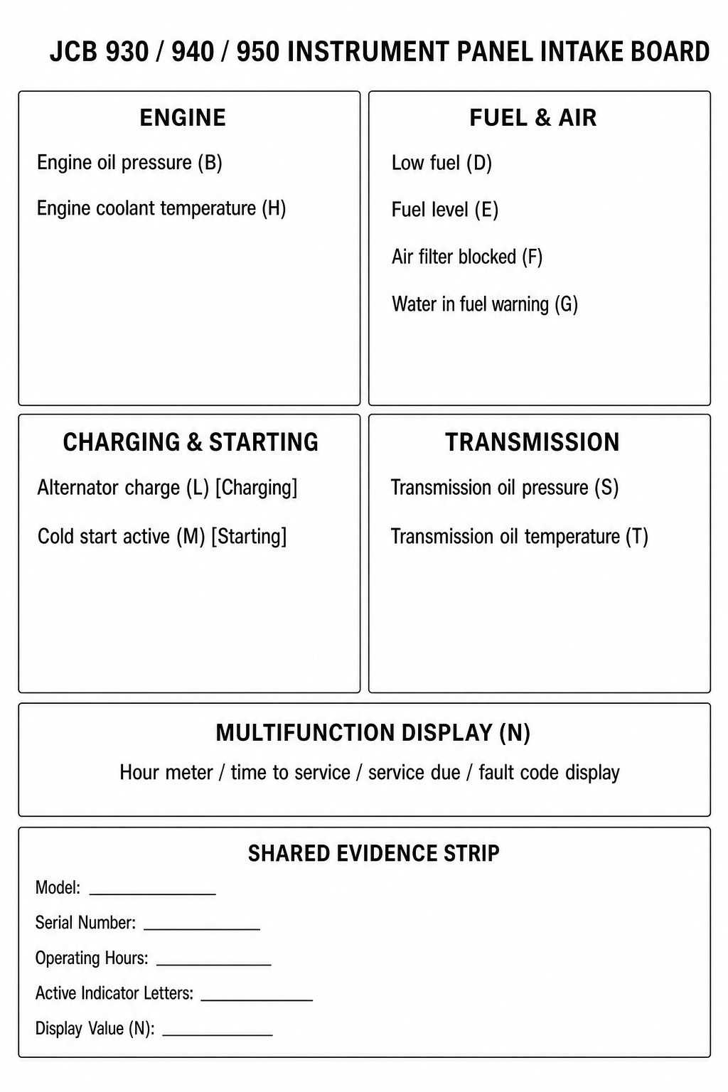
Editorial layout illustrating the instrument panel indicator groups on JCB rough-terrain forklifts and the evidence required for qualified service dispatch.
On JCB 930, 940, and 950 rough-terrain forklifts, the instrument cluster indexes engine conditions, transmission metrics, fuel and air filtration states, alternator charging, cold starting, and neutral display data into separate visual positions. Identifying the exact indicator position provides clear intake evidence for dealer service teams without inferring unstated repair procedures or fault thresholds.
1
1. Identify the Active Panel Indicator Position
Locate the specific illuminated indicator on the instrument panel: Engine Oil Pressure (B) or Engine Coolant Temperature (H) for the engine; Transmission Oil Pressure (S) or Transmission Oil Temperature (T) for the transmission; Air Filter Blocked (F) or Water in Fuel (G) for intake/fuel; Alternator Charge (L) for charging; Cold Start Active (M) for starting; Amber Warning (A); or Critical Stop (Q).
2
2. Record Multi-Function Display Readings
Inspect panel position N, designated by JCB as the neutral Hour meter / time to service / service due / fault code display. Record any active alphanumeric codes, service indicators, or hour meter values shown on the display.
3
3. Consult the Operator's Manual for Operating Directives
Reference the official JCB Operator's Manual for specific operational safety instructions and required machine responses, as the Quick Reference Guide serves strictly as an indicator index and does not define operating procedures.
4
4. Provide Panel Data to Authorized Service
Compile the machine model, serial number, recorded panel indicator letters, and multi-function display values (N) to provide an accurate intake summary to authorized service personnel.
JCB 930/940/950 Instrument Panel Indicator Index
Indicator Position
Subsystem
OEM Designation
Indicator A
General Warning
Amber warning
Indicator B
Engine System
Engine oil pressure
Indicator D & E
Fuel System
Low fuel (D) and Fuel level (E)
Indicator F
Air Intake System
Air filter blocked
Indicator G
Fuel System
Water in fuel warning
Indicator H
Engine System
Engine coolant temperature
Indicator L
Charging System
Alternator charge
Indicator M
Starting System
Cold start active
Indicator N
Neutral Display
Hour meter / time to service / service due / fault code display
Indicator Q
General Warning
Critical stop
Indicator S
Transmission System
Transmission oil pressure
Indicator T
Transmission System
Transmission oil temperature
Independent Engine and Transmission Indicator Layout
On JCB 930, 940, and 950 rough-terrain forklifts, the instrument panel provides distinct, dedicated indicators for engine and transmission subsystems rather than a combined powertrain light. Engine oil pressure (B) and engine coolant temperature (H) are assigned separate visual positions from transmission oil pressure (S) and transmission oil temperature (T).
Recording the precise letter position and icon on the panel ensures that service technicians know whether the alert originated from the engine or the transmission system.
Engine Indicators: Indicator B (Engine oil pressure) and Indicator H (Engine coolant temperature).
Transmission Indicators: Indicator S (Transmission oil pressure) and Indicator T (Transmission oil temperature).
Air and Fuel Indicators: Indicator F (Air filter blocked), Indicator G (Water in fuel warning), and Indicator D (Low fuel).
Charging and Starting Indicators: Indicator L (Alternator charge) and Indicator M (Cold start active).
General Warning Indicators: Indicator A (Amber warning) and Indicator Q (Critical stop).
Functions of Charging, Starting, and the Multi-Function Display
The instrument panel distinguishes electrical charging and starting indicators from the central display. Indicator L designates Alternator charge, while Indicator M designates Cold start active. Position N is a neutral display area functioning as the hour meter, time to service countdown, service due indicator, and fault code display.
Capturing the exact alphanumeric characters shown on neutral display Item N provides verified data for service triage when communicating with dealer personnel.
Quick Reference Guide Scope and Operator Manual Authority
The JCB Quick Reference Guide Revision 1.0 explicitly states: 'This Quick Reference Guide DOES NOT replace the Operators Manual. You MUST read ALL the disclaimers and safety and other instructions in the Operators Manual before initially operating this product.'
Because the Quick Reference Guide is an indicator layout index rather than an operational manual, it supplies no diagnostic flowcharts, fault thresholds, or mechanical repair procedures. All operating responses and safety directives remain governed by the official Operator's Manual.
Sources and limits
JCB 930, 940, 950 Quick Reference Guide (Rev 1.0)Official JCB operator instrument panel reference guide, revision 1.0 (dated 1/6/2021). Locators: PDF page 1 (Instrument Panel A–T) and PDF page 2 (Service Points & Best Practices).
JCB Machines Quick Start Guides PortalOfficial JCB portal defining scope, intended use, and limitations of Quick Start Guides relative to full Operator's Manuals.
Applies specifically to JCB 930, 940, and 950 rough-terrain forklifts equipped with the standard instrument panel described in JCB Quick Reference Guide Revision 1.0. This guide provides indicator identification for service intake and does not substitute for the JCB Operator's Manual.